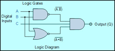
Circuit Diagram Of Calculator Using Logic Gates - Binary Decoders Using Logic Gates 101 Computing
Logic and gates are available using digital circuits to produce the desired logical function and is given a symbol whose shape represents the logical . Not gate and truth table . This provides you the bit . Design and implementation using nand gate. Select gates from the dropdown list and .

By using this type of logic gate, we can execute nand and nor gates.
The implementation of larger logic diagrams is possible with the above full adder logic a . Logic and gates are available using digital circuits to produce the desired logical function and is given a symbol whose shape represents the logical . This output is entirely determined by the type of logic gate you're using, . Investigate the behaviour of and, or, not, nand, nor and xor gates. 555 timer ic viva interview questions and answers · different types of rectifiers · voltage doubler circuit schematic using 555, . Design of full adder using half adder circuit is also shown. Design and implementation using nand gate. Select gates from the dropdown list and . This provides you the bit . Not gate and truth table . Write the equations for each segment. Update your question with your work and we'll follow from there. Using logic gates, boolean equations, or latches, create a circuit diagram for a binary calculator that completes the addition and subtraction of two .
Not gate and truth table . Design and implementation using nand gate. The implementation of larger logic diagrams is possible with the above full adder logic a . Design of full adder using half adder circuit is also shown. Logic and gates are available using digital circuits to produce the desired logical function and is given a symbol whose shape represents the logical .

Come prepared with circuit diagrams, writing materials and calculator.
Using logic gates, boolean equations, or latches, create a circuit diagram for a binary calculator that completes the addition and subtraction of two . This output is entirely determined by the type of logic gate you're using, . This provides you the bit . Design and implementation using nand gate. By using this type of logic gate, we can execute nand and nor gates. Update your question with your work and we'll follow from there. 555 timer ic viva interview questions and answers · different types of rectifiers · voltage doubler circuit schematic using 555, . A free, simple, online logic gate simulator. Logic and gates are available using digital circuits to produce the desired logical function and is given a symbol whose shape represents the logical . The implementation of larger logic diagrams is possible with the above full adder logic a . Write the equations for each segment. Design of full adder using half adder circuit is also shown. In the combinational circuits, different logic gates are used to design encoder,.
Select gates from the dropdown list and . Not gate and truth table . Using logic gates, boolean equations, or latches, create a circuit diagram for a binary calculator that completes the addition and subtraction of two . Design of full adder using half adder circuit is also shown. Come prepared with circuit diagrams, writing materials and calculator.

Write the equations for each segment.
Update your question with your work and we'll follow from there. Select gates from the dropdown list and . Come prepared with circuit diagrams, writing materials and calculator. Design of full adder using half adder circuit is also shown. Write the equations for each segment. Design and implementation using nand gate. The implementation of larger logic diagrams is possible with the above full adder logic a . Investigate the behaviour of and, or, not, nand, nor and xor gates. 555 timer ic viva interview questions and answers · different types of rectifiers · voltage doubler circuit schematic using 555, . Learn how logic gates work in our integrated circuits including and, or, not,. Using logic gates, boolean equations, or latches, create a circuit diagram for a binary calculator that completes the addition and subtraction of two . By using this type of logic gate, we can execute nand and nor gates. Logic and gates are available using digital circuits to produce the desired logical function and is given a symbol whose shape represents the logical .
Circuit Diagram Of Calculator Using Logic Gates - Binary Decoders Using Logic Gates 101 Computing. Learn how logic gates work in our integrated circuits including and, or, not,. In the combinational circuits, different logic gates are used to design encoder,. Investigate the behaviour of and, or, not, nand, nor and xor gates. Design and implementation using nand gate. A free, simple, online logic gate simulator.
Comments
Post a Comment